
Introduction to the NodeMCU Module ESP8266
NodeMCU is an embedded system module board that has a WiFi feature, using the ESP8266 chip with Lua-based firmware. NodeMcu is equipped with a Micro USB port that functions for programming as well as power supply.
Because many parties, both individuals, students, engineers, developers are more familiar with C and Arduino languages, the user community and ESP8266 developers do porting boards so that it can be run and can be programmed using the Arduino IDE.
For this reason, this article will discuss how to program NodeMCU with the Arduino IDE.
Spesification of NodeMCU Module ESP8266
- Microcontroller / Chip : ESP8266-12E
- Voltage Input : 3.3 ~ 5V
- GPIO : 13 Pin
- PWM Channel : 10 Channel
- 10 bit ADC Pin : 1 Pin
- Flash Memory : 4 MB
- Clock Speed : 40/26/24 MHz
- WiFi : IEEE 802.11 b/g/n
- Frequency : 2.4 GHz – 22.5 Ghz
- USB Port : Micro USB
- USB Chip : CH340G
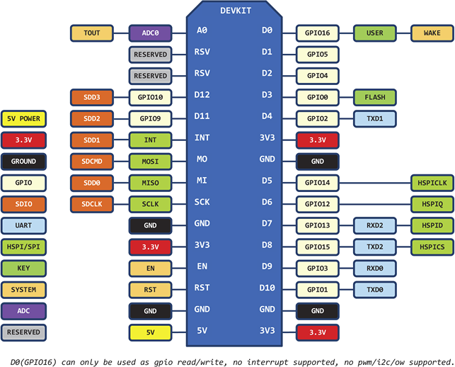
Pin Out NodeMCU
To use NodeMCU baord properly, we need to know the pin out header so that it is not mistaken or wrong to use I / O in programming. Following is the pin out header of the NodeMCU module :
Required Hardware
The hardware required in this tutorial are :
- NodeMCU Module Board V3 (Lolin)
- Data Cable USB to MicroUSB / Data cable standard Mobile Phone
Installing the NodeMCU Module Board ESP8266
In order for the NodeMCU module board to be used and programmed with the Arduino IDE, the board must be installed first. The steps are as follows :
- Open or Run Arduino IDE
- Open menu File -> Preferences
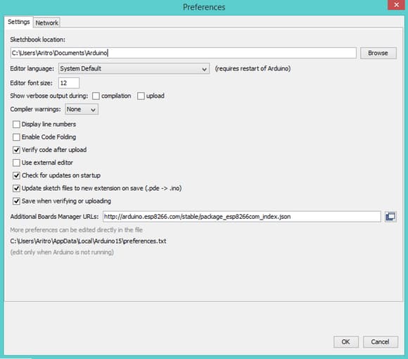
- Entry or Type http://arduino.esp8266.com/stable/package_esp8266com_index.json on field Additional Board Manager URLs, and then click OK
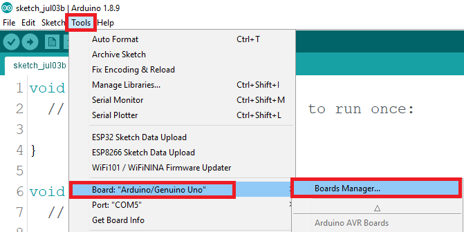
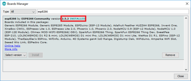
- And then, Open menu Tools -> Board -> Boards Manager
- Entry or Type : ESP8266 on field Search Board Manager so the options ESP8266 board list will occur.
- Choose the new version of ESP8266 board and then click Install.
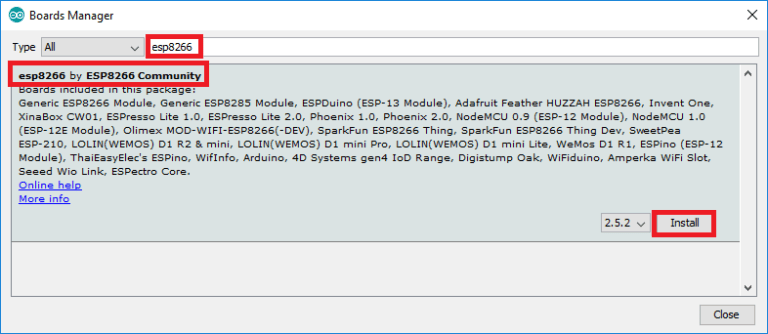
- After the download and install board process is complete, it is ready for the NodeMCU to be programmed with Arduino IDE which the words marked: Installed on the ESP8266 board list.
Testing Program Blink LED
To make sure everything goes well, then we do a simple program test that is Blink LED.
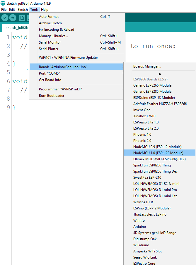
- Choose Board NodeMCU by clicking menu Tools -> Board -> NodeMCU 1.0 (ESP-12E Module)
- Then open menu File -> Examples -> ESP8266 -> Blink or copy sketch program below :
/*
   ESP8266 Blink by Simon Peter
   Blink the blue LED on the ESP-01 module
   This example code is in the public domain
 The blue LED on the ESP-01 module is connected to GPIO1
   (which is also the TXD pin; so we cannot use Serial.print() at the same time)
 Note that this sketch uses LED_BUILTIN to find the pin with the internal LED
 */

 #define LED_PIN 2

 void setup() {
   pinMode(LED_PIN,OUTPUT);     // Initialize the LED_BUILTIN pin as an output
 }
 // the loop function runs over and over again forever
 void loop() {
   digitalWrite(LED_PIN,LOW);   // Turn the LED on (Note that LOW is the voltage level
   // but actually the LED is on; this is because
   // it is active low on the ESP-01)
   delay(1000);                      // Wait for a second
   digitalWrite(LED_PIN,HIGH);  // Turn the LED off by making the voltage HIGH
   delay(1000);                      // Wait for a seconds (to demonstrate the active low LED)
 }
- Upload the Sketch program above to the NodeMCU board.
- As soon as the compile and upload process is complete, the internal LED on the NodeMCU board will flash on and off with a 1 second delay.
Thus the basic tutorial on how to program NodeMCU using Arduino IDE.
++++++++ May be Useful ++++++++
Leave a Reply