
About ACS712
ACS712 is a sensor module to measure current both AC current and DC current using Hall Effect technology. What is meant by the Hall Effect is to flow the load path measured through a copper conduction medium to produce a magnetic field.
The magnetic field is then converted into a voltage proportional to the current flowing by an IC Hall. The ACS712 sensor module has 3 variants :
- ACS712-05B for current measurements in the range of -5A to 5A
- ACS712-20A for current measurements in the range of -20A to 20A
- ACS712-30A for current measurements in the range of -30A to 30A
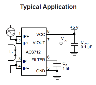
The following figure shows the Typical Application of the ACS712 sensor module.
With a high level of accuracy, an affordable price and a small size, making the ACS712 module very suitable for use in a variety of applications and projects, among others :
- Motor control
- Load current detection and management
- Switching Power Supply
- Overcurrent disturbance protection
- etc
In the picture above is a sensitivity chart datasheet of each sensor ACS712 5A, ACS712 20A and ACS712 30A. From these linear graphs, conclusions can be drawn :
- Offset voltage output = 2,5V
- ACS712 5A has sensitivity 185 mV/A
- ACS712 20A has sensitivity 100 mV/A
- ACS712 30A has sensitivity 66 mV/A
Because the sensitivity data of each ACS712 is different, the programming must also be adjusted to the type of ACS712 used by referring to the sensitivity data.
While the sample program in this article is used ACS712 20A, if using another type of ACS712, please replace the formula referring to the sensitivity data from ACS712 used so that the measurement results are correct.
ACS712 Specifications
The following are the specifications and features of the ACS712 sensor :
- Low-noise analog signal path
- Device bandwidth is set via the new FILTER pin
- 5 μs output rise time in response to step input current
- 80 kHz bandwidth
- Total output error 1.5% at TA = 25°C
- Small footprint, low-profile SOIC8 package
- 1.2 mΩ internal conductor resistance
- 2.1 kVRMS minimum isolation voltage from pins 1-4 to pins 5-8
- 5.0 V, single supply operation
- 66 to 185 mV/A output sensitivity
- Output voltage proportional to AC or DC currents
- Factory-trimmed for accuracy
- Extremely stable output offset voltage
- Nearly zero magnetic hysteresis
- Ratiometric output from supply voltage
Hardware Required
The hardware required in the example program ACS712 with Arduino in this tutorial, among others :
- Current Sensor Module ACS712 5A / ACS712 20A / ACS712 30A
- Arduino UNO / Arduino Nano / Arduino Pro Mini
- Some M-F / F-F jumper cables
- Load can use Lights / Drills / Power Supply + Cable
Circuit / Wiring Diagram
Following is the circuit connection between the ACS712 module and Arduino
| Modul ACS712 | Arduino |
| VCC | +5V |
| GND | GND |
| OUT | A0 |
Program Code
- DC Current Measurement
/*
Measuring DC Current Using ACS712 - www.nn-digital.com
*/
const int analogIn = A0;
int mVperAmp = 100; // 185 = ACS712 5A, 100 = ACS712 20A, 66 = ACS712-30A
int RawValue= 0;
int ACSoffset = 2500;
double Voltage = 0;
double Amps = 0;

void setup(){
     Serial.begin(9600);
     pinMode(analogIn, INPUT);
}

void loop(){
     RawValue = analogRead(analogIn);
     Voltage = (RawValue / 1023) * 5000; // Voltage ( mV )
     Amps = ((Voltage - ACSoffset) / mVperAmp);
    // Display the Value to Serial Monitor Window
    Serial.print("Raw Value = " ); // shows pre-scaled value
    Serial.println(RawValue);
    Serial.print("mV = "); // shows the voltage measured
    Serial.println(Voltage,3); // display 3 digits after decimal point
    Serial.print("Amps = "); // shows the voltage measured
    Serial.println(Amps,3); // display 3 digits after decimal point
    delay(2500);
 }
- AC Current Measurement
/*
Measuring AC Current Using ACS712 - www.nn-digital.com
*/
const int analogIn = A0;
int mVperAmp = 100; // 185 = ACS712 5A, 100 = ACS712 20A, 66 = ACS712-30A
int ACSoffset = 2500;
double Voltage = 0;

float amplitude_current;               //amplitude current
float effective_value;       //effective current

void setup()
{
     Serial.begin(9600);
     pinMode(analogIn, INPUT);
}

void loop()
{
     int sensor_max;
     sensor_max = getMaxValue();

     Serial.print("Sensor_max = ");
     Serial.println(sensor_max);

     Voltage = (sensor_max / 1023) * 5000; // Voltage ( mV )
     amplitude_current = ((Voltage - ACSoffset) / mVperAmp);
     effective_value = amplitude_current / 1.414;

     Serial.print("Current Max (A) : ");
     Serial.println(amplitude_current,6);//6 number after the decimal point
     Serial.print("Current RMS (A) : ");
     Serial.println(effective_value,6);
     Serial.println();
}

/*
Function: Sampling 5000ms and get the maximum value from A0 pin
*/
int getMaxValue()
{
     int sensorValue;             //value read from the sensor
     int sensorMax = 0;
     uint32_t start_time = millis();
     while((millis()-start_time) < 5000)
     {
         sensorValue = analogRead(analogIn);
         if (sensorValue > sensorMax)
         {
             //record the maximum sensor value
             sensorMax = sensorValue;
         }
     }
     return sensorMax;
}
After the sketch of the above program is uploaded to the Arduino board, open the Serial Monitor on the Baudrate 9600 of the Arduino IDE to see the measured current reading.
In addition to the ACS712 Module, there are several other electronic modules that we can use to measure electrical current, namely the INA219 and PZEM-004T modules. To find out more details about the two modules and their sample programs, please open the following article :
- Learn INA219 Current, Voltage & Power Sensor Modules with Arduino
- Get to know PZEM-004T Electronic Modules for Electrical Measurement Tools
Thus our tutorial this time about programming the AC-DC current sensor module ACS712 using Arduino.
++++++++ May be Useful ++++++++
Leave a Reply