
Get to know the MQ2 / MQ-2 Sensor
MQ2 is a sensor module that can be used to detect flammable fumes or gases at concentrations between 200 ppm – 10,000 ppm. What is ppm? ppm stands for “part per million”, which is a unit that states the amount or concentration of substances in every 1 million. Almost the same as the unit of percent (%) which means “per cent”. Usually ppm is used to measure the concentration of substances in a liquid or air / gas. 1 ppm is equivalent to 1 mg / L or 1 mg / Kg.
Gases that can be detected by MQ2 include LPG, Hydrogen (H2), Methane (CH4), Carbon Monoxide (CO), Alcohol, Smoke (Smoke) and Propane. This sensor is designed for indoor use at room temperature. Usually applied to the combustible gas leak detection equipment in a house, agency, warehouse or industrial factory.
In the previous article, that is :
Example of the MQ2 MQ-2 Smoke / Gas Sensor Program with Arduino
using only the MQ2 sensor module to detect / create gas alarms that are detected at a certain level, the following article will present an example of a more detailed MQ2 program that measures the concentration of each gas detected according to the datasheet of the MQ2 sensor.
How MQ2 / MQ-2 works
MQ2 or MQ-2 is a Metal Oxide Semiconductor (MOS) type gas sensor or also known as Chemiresistors because the detection is based on changing the resistance value of the material / material from the sensor when the material / material is in contact with the gas detected.
By using a voltage divider circuit construction, the content of a gas can be measured / obtained. The resistance value of the MQ2 sensor is directly proportional to the level or concentration of a gas detected.
Because it is made or arranged into a voltage divider circuit, the voltage value of the sensor will automatically follow or be proportional to the value of the resistance. Well, from this voltage value that can then be read with a microcontroller like Arduino, STM32, NodeMCU ESP8266 or Raspberry Pi.
Specification
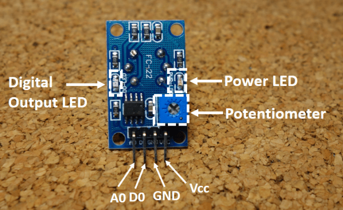
- Power indikator LED
- TTL sinyal output LED
- Digital output DO
- Analog output AO
- TTL output (DO) aktif Low
- Semakin banyak onsentrasi gas terdeteksi maka tegangan AO semakin tinggi
- dimensi : 32 (L) * 20 (W) * 22 (H)
- Input voltage : DC5V
- Power consumption ( current ) : 150mA
- DO output : TTL digital 0 and 1 (0.1 and 5V)
- AO output : 0.1 – 4 V
Hardware Required
- Arduino Uno / Arduino Nano / Arduino Pro Mini
- MQ2 Sensor Modul
- Some Dupont M-F or F-F jumper cables
Circuit / Wiring Diagram
| MQ2 | Arduino |
| 5V | 5V |
| GND | GND |
| A0 | A0 |
MQ2 calibration
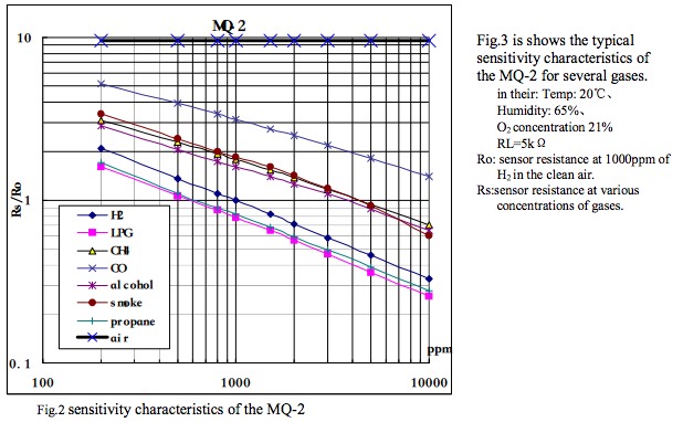
To be able to measure the concentration of the gas detected by the MQ2 sensor, we must calibrate based on the MQ2 datasheet in the form of a straight line curve of the sensitivity of MQ2 to some of the gases detected as shown below :
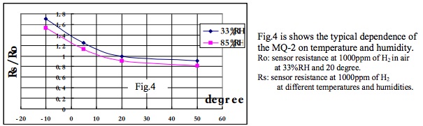
The second curve shows the characteristics of the MQ2 sensor on temperature and humidity.
Program Code
Copy the following program, then upload it to the Arduino board and we must first do it in a clean air condition for calibration so that the Ro value from the sensor can be obtained. The Ro value obtained can then be used in measuring the concentration of gas detected in the air.
/*******************Demo for MQ-2 Gas Sensor Module V1.0*****************************
Support:  Tiequan Shao: support[at]sandboxelectronics.com

Lisence: Attribution-NonCommercial-ShareAlike 3.0 Unported (CC BY-NC-SA 3.0)

Note:    This piece of source code is supposed to be used as a demostration ONLY. More
         sophisticated calibration is required for industrial field application.

                                                    Sandbox Electronics    2011-04-25
************************************************************************************/

/************************Hardware Related Macros************************************/
#define         MQ_PIN                       (0)     //define which analog input channel you are going to use
#define         RL_VALUE                     (5)     //define the load resistance on the board, in kilo ohms
#define         RO_CLEAN_AIR_FACTOR          (9.83)  //RO_CLEAR_AIR_FACTOR=(Sensor resistance in clean air)/RO,
                                                     //which is derived from the chart in datasheet

/***********************Software Related Macros************************************/
#define         CALIBARAION_SAMPLE_TIMES     (50)    //define how many samples you are going to take in the calibration phase
#define         CALIBRATION_SAMPLE_INTERVAL  (500)   //define the time interal(in milisecond) between each samples in the
                                                     //cablibration phase
#define         READ_SAMPLE_INTERVAL         (50)    //define how many samples you are going to take in normal operation
#define         READ_SAMPLE_TIMES            (5)     //define the time interal(in milisecond) between each samples in
                                                     //normal operation

/**********************Application Related Macros**********************************/
#define         GAS_LPG                      (0)
#define         GAS_CO                       (1)
#define         GAS_SMOKE                    (2)

/*****************************Globals***********************************************/
float           LPGCurve[3]  =  {2.3,0.21,-0.47};   //two points are taken from the curve.
                                                    //with these two points, a line is formed which is "approximately equivalent"
                                                    //to the original curve.
                                                    //data format:{ x, y, slope}; point1: (lg200, 0.21), point2: (lg10000, -0.59)
float           COCurve[3]  =  {2.3,0.72,-0.34};    //two points are taken from the curve.
                                                    //with these two points, a line is formed which is "approximately equivalent"
                                                    //to the original curve.
                                                    //data format:{ x, y, slope}; point1: (lg200, 0.72), point2: (lg10000,  0.15)
float           SmokeCurve[3] ={2.3,0.53,-0.44};    //two points are taken from the curve.
                                                    //with these two points, a line is formed which is "approximately equivalent"
                                                    //to the original curve.
                                                    //data format:{ x, y, slope}; point1: (lg200, 0.53), point2: (lg10000,  -0.22)
float           Ro           =  10;                 //Ro is initialized to 10 kilo ohms

void setup()
{
  Serial.begin(9600);                               //UART setup, baudrate = 9600bps
  Serial.print("Calibrating...\n");
  Ro = MQCalibration(MQ_PIN);                       //Calibrating the sensor. Please make sure the sensor is in clean air
                                                    //when you perform the calibration
  Serial.print("Calibration is done...\n");
  Serial.print("Ro=");
  Serial.print(Ro);
  Serial.print("kohm");
  Serial.print("\n");
}

void loop()
{
   Serial.print("LPG:");
   Serial.print(MQGetGasPercentage(MQRead(MQ_PIN)/Ro,GAS_LPG) );
   Serial.print( "ppm" );
   Serial.print("    ");
   Serial.print("CO:");
   Serial.print(MQGetGasPercentage(MQRead(MQ_PIN)/Ro,GAS_CO) );
   Serial.print( "ppm" );
   Serial.print("    ");
   Serial.print("SMOKE:");
   Serial.print(MQGetGasPercentage(MQRead(MQ_PIN)/Ro,GAS_SMOKE) );
   Serial.print( "ppm" );
   Serial.print("\n");
   delay(200);
}

/****************** MQResistanceCalculation ****************************************
Input:   raw_adc - raw value read from adc, which represents the voltage
Output:  the calculated sensor resistance
Remarks: The sensor and the load resistor forms a voltage divider. Given the voltage
         across the load resistor and its resistance, the resistance of the sensor
         could be derived.
************************************************************************************/
float MQResistanceCalculation(int raw_adc)
{
  return ( ((float)RL_VALUE*(1023-raw_adc)/raw_adc));
}

/***************************** MQCalibration ****************************************
Input:   mq_pin - analog channel
Output:  Ro of the sensor
Remarks: This function assumes that the sensor is in clean air. It use
         MQResistanceCalculation to calculates the sensor resistance in clean air
         and then divides it with RO_CLEAN_AIR_FACTOR. RO_CLEAN_AIR_FACTOR is about
         10, which differs slightly between different sensors.
************************************************************************************/
float MQCalibration(int mq_pin)
{
  int i;
  float val=0;

  for (i=0;i<CALIBARAION_SAMPLE_TIMES;i++) {            //take multiple samples
    val += MQResistanceCalculation(analogRead(mq_pin));
    delay(CALIBRATION_SAMPLE_INTERVAL);
  }
  val = val/CALIBARAION_SAMPLE_TIMES;                   //calculate the average value

  val = val/RO_CLEAN_AIR_FACTOR;                        //divided by RO_CLEAN_AIR_FACTOR yields the Ro
                                                        //according to the chart in the datasheet

  return val;
}
/*****************************  MQRead *********************************************
Input:   mq_pin - analog channel
Output:  Rs of the sensor
Remarks: This function use MQResistanceCalculation to caculate the sensor resistenc (Rs).
         The Rs changes as the sensor is in the different consentration of the target
         gas. The sample times and the time interval between samples could be configured
         by changing the definition of the macros.
************************************************************************************/
float MQRead(int mq_pin)
{
  int i;
  float rs=0;

  for (i=0;i<READ_SAMPLE_TIMES;i++) {
    rs += MQResistanceCalculation(analogRead(mq_pin));
    delay(READ_SAMPLE_INTERVAL);
  }

  rs = rs/READ_SAMPLE_TIMES;

  return rs;
}

/*****************************  MQGetGasPercentage **********************************
Input:   rs_ro_ratio - Rs divided by Ro
         gas_id      - target gas type
Output:  ppm of the target gas
Remarks: This function passes different curves to the MQGetPercentage function which
         calculates the ppm (parts per million) of the target gas.
************************************************************************************/
int MQGetGasPercentage(float rs_ro_ratio, int gas_id)
{
  if ( gas_id == GAS_LPG ) {
     return MQGetPercentage(rs_ro_ratio,LPGCurve);
  } else if ( gas_id == GAS_CO ) {
     return MQGetPercentage(rs_ro_ratio,COCurve);
  } else if ( gas_id == GAS_SMOKE ) {
     return MQGetPercentage(rs_ro_ratio,SmokeCurve);
  }

  return 0;
}

/*****************************  MQGetPercentage **********************************
Input:   rs_ro_ratio - Rs divided by Ro
         pcurve      - pointer to the curve of the target gas
Output:  ppm of the target gas
Remarks: By using the slope and a point of the line. The x(logarithmic value of ppm)
         of the line could be derived if y(rs_ro_ratio) is provided. As it is a
         logarithmic coordinate, power of 10 is used to convert the result to non-logarithmic
         value.
************************************************************************************/
int  MQGetPercentage(float rs_ro_ratio, float *pcurve)
{
  return (pow(10,( ((log(rs_ro_ratio)-pcurve[1])/pcurve[2]) + pcurve[0])));
}
After the program or sketch has been uploaded successfully, observe the results by opening the Serial Monitor at baudrate : 9600 bps.
Thus the tutorial is more detailed or deeper than the use of MQ2 sensors to measure the content or concentration of gases : LPG, Hydrogen (H2), Methane (CH4), Carbon Monoxide (CO), Alcohol, Smoke (Asap) dan Propane in the air.
+++++ May be Useful +++++
Leave a Reply